运算放大器 (Op Amp) 是一个简写术语,指的是运算放大器。运算放大器是一种电路元件,可以放大两个输入电压之间的差值
- Vo = A (V2 - V1)
运算放大器通常被封装成一个 8 引脚集成电路。
 运算放大器 IC 芯片
| 引脚 |
用途 |
| 1 |
偏移抵消 |
| 2 |
反相输入 |
| 3 |
同相输入 |
| 4 |
-V 电源 |
| 5 |
无用 |
| 6 |
输出 |
| 7 |
+V 电源 |
| 8 |
无用 |
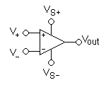
运算放大器符号
 运算放大器
运算放大器
- V+: 同相输入
- V−: 反相输入
- Vout: 输出
- VS+: 正电源
- VS−: 负电源
运算放大器比简单的双极结型晶体管更能放大交流信号或交流电压。
从上面
- V0 = A (V2 - V1)
- V2 > V1 , V0 = +Vss
- V2 < V1 , V0 = -Vss
- V2 = V1 , V0 = 0
其中一个电压接地
- 如果 V2 = 0 , V0 = -A V1 。反相放大器
其中一个电压接地
- 如果 V1 = 0 , V0 = A V2 。同相放大器
 差分放大器
差分放大器

- 差分
 (两个输入引脚之间) =
每当  并且
并且  ,
,

当  以及
以及  (包括先前的条件,使得
  )
)

 反相放大器
反相放大器

反相放大倍数由两个电阻的比例决定
 同相放大器
同相放大器

同相放大倍数由两个电阻的比例加1决定
 电压跟随器
电压跟随器
从同相放大器的公式来看。如果电阻具有相同的阻值,则输出电压完全等于输入电压。

从反相放大器的公式来看。如果电阻具有相同的阻值,则输出电压完全等于输入电压并被反转。

 加法器
加法器

当  且
且  相互独立。
相互独立。

当 

 积分放大器
积分放大器
对(反转的)信号进行时间积分

(其中  和
和  是时间的函数,
 是积分器在时间 *t* = 0 时的输出电压。)
 微分放大器
微分放大器
对(反转的)信号进行时间微分。
“微分器”这个名称不应该与本页也显示的“差分放大器”混淆。

(其中 和 是时间的函数)
 比较器
比较器

从 V0 = A (V2 - V1)
- Vo = Vss
- Vo = V-ss
当两个输入电压相等时,输出电压为零。当两个输入电压不同且一个大于或小于另一个时
- Vo = Vss 当 V2 > V1
- Vo = V-ss 当 V2 < V1
 仪表放大器
仪表放大器
结合了非常高的输入阻抗、高共模抑制比、低直流偏移等特性,用于进行非常精确、低噪声的测量。
 施密特触发器
一个具有滞后的比较器。
滞后从 到
到  .
.
 电感旋量器
电感旋量器
旋量器可以变换阻抗。这里电容被转换成电感器。

分压器参考电压
 负阻抗转换器
为任何信号发生器创建一个具有负值的电阻。
- 在这种情况下,输入电压与输入电流(因此输入电阻)之间的比率由下式给出:

 超级二极管
超级二极管
对于负载(这里用一个通用电阻 表示)表现为一个理想二极管。
- 这种基本配置有一些局限性。有关更多信息以及实际使用的配置,请参阅主条目。
 峰值检测器
峰值检测器
当开关闭合时,输出变为零伏。当开关打开一定时间间隔时,电容器将充电到该时间间隔内达到的最大输入电压。
电容器的充电时间必须远小于输入电压中最高可观频率分量的周期。
 对数配置
对数配置
- 输入电压
 和输出电压
和输出电压  之间的关系为

其中  是饱和电流。
- 如果运算放大器被认为是理想的,则负极虚拟接地,因此流过电阻的电流(来自电源,并因此流过二极管到输出,因为运算放大器输入不吸收电流)为

其中  是流过二极管的电流。众所周知,二极管的电流和电压之间的关系为

当电压大于零时,这可以用以下公式近似

将这两个公式结合起来,并考虑到输出电压 是二极管两端电压  的反值,因此证明了这种关系。
请注意,此实现并未考虑温度稳定性和其他非理想因素。
 指数配置
指数配置
- 输入电压 和输出电压 之间的关系为

其中 是饱和电流。
- 考虑到运算放大器是理想的,则负极虚拟接地,因此流过二极管的电流为
当电压大于零时,它可以用以下公式近似
输出电压为


